%20-%20https://sketchapp.com%20--%3E%20%20%20%20%3Ctitle%3EBranding%20/%20Logo%3C/title%3E%20%20%20%20%3Cdesc%3ECreated%20with%20Sketch.%3C/desc%3E%20%20%20%20%3Cg%20id=%22Branding-/-Logo%22%20stroke=%22none%22%20stroke-width=%221%22%20fill=%22none%22%20fill-rule=%22evenodd%22%3E%20%20%20%20%20%20%20%20%3Cg%20id=%22first-5-minutes-logo%22%3E%20%20%20%20%20%20%20%20%20%20%20%20%3Cpath%20d=%22M107.5,28.25%20C108.802538,28.2657216%20110.089654,28.5340122%20111.29,29.04%20L106.95,47.2%20C106.416667,47.16%20105.906667,47.14%20105.42,47.14%20C102.102593,47.132391%2098.8327036,47.9284187%2095.89,49.46%20C92.8237926,51.058036%2090.4349524,53.7059926%2089.16,56.92%20L83.53,88.8%20L64.45,88.8%20L75,28.85%20L93.44,28.85%20L90.87,42.92%20C92.1521941,38.9871481%2094.3057272,35.3945079%2097.17,32.41%20C99.8838057,29.6453506%20103.627609,28.1376816%20107.5,28.25%20Z%20M179.46,28.86%20L196.59,28.82%20L194.49,41.03%20C194.221622,42.5979695%20192.860768,43.7432837%20191.27,43.74%20L176.78,43.74%20L172.38,68.36%20C172.3,68.76%20172.19,69.15%20172.19,69.51%20C172.149283,69.8953165%20172.129254,70.2825389%20172.13,70.67%20C172.084212,71.921077%20172.520987,73.1419017%20173.35,74.08%20C174.321652,75.036912%20175.660362,75.5257054%20177.02,75.42%20C178.751367,75.4196302%20180.476639,75.2148802%20182.16,74.81%20C183.955348,74.3784095%20185.714075,73.806656%20187.42,73.1%20L189.01,85.82%20C186.510979,87.0733742%20183.886373,88.0588582%20181.18,88.76%20C178.150562,89.5739552%20175.026877,89.9841699%20171.89,89.98%20C165.963333,89.9733333%20161.333333,88.2866667%20158,84.92%20C154.696208,81.5282123%20152.906867,76.943027%20153.04,72.21%20C153.04,71.4%20153.08,70.56%20153.16,69.71%20C153.234995,68.9099025%20153.358556,68.1151034%20153.53,67.33%20L157.69,43.78%20L160.26,28.86%20L163.19,12.6%20L182.27,12.6%20L179.46,28.86%20Z%20M34.65,28.86%20L68.66,28.86%20L58.14,88.8%20L39.05,88.8%20L47,43.42%20L32.08,43.42%20L25.85,85.16%20C24.9530739,90.2742838%2023.7881358,95.337926%2022.36,100.33%20C21.1749985,104.630813%2019.3188441,108.717728%2016.86,112.44%20C14.5880331,115.801782%2011.5204115,118.549932%207.93,120.44%20C5.44450646,121.705671%202.76373971,122.544044%20-1.42108547e-14,122.92%20L13,43.42%20L1.87,43.42%20L4,31.57%20C4.26643407,30.0131678%205.61057408,28.8712809%207.19,28.86%20L15.57,28.86%20L15.94,26.78%20C17.5733333,17.2533333%2020.86,10.41%2025.8,6.25%20C30.74,2.09%2037.6133333,0.01%2046.42,0.01%20C49.7735935,0.0189807286%2053.1198714,0.323492017%2056.42,0.92%20C59.6819981,1.48622388%2062.8513186,2.49556163%2065.84,3.92%20L62.3,17.85%20C60.108627,16.8563064%2057.8101715,16.1181163%2055.45,15.65%20C53.1131588,15.1733774%2050.7349355,14.9288558%2048.35,14.92%20C44.68,14.92%2041.76,15.83%2039.59,17.67%20C37.42,19.51%2035.9,22.62%2035,27.03%20L34.65,28.86%20Z%20M145.17,57.97%20C146.683662,59.5156093%20147.972904,61.2660157%20149,63.17%20C150.040886,65.2075136%20150.556484,67.4727057%20150.5,69.76%20C150.54143,72.7721081%20149.855342,75.7497288%20148.5,78.44%20C147.218249,80.9446064%20145.377435,83.120736%20143.12,84.8%20C140.691687,86.5857789%20137.956436,87.9110369%20135.05,88.71%20C131.79693,89.62895%20128.430293,90.083446%20125.05,90.06%20C121.326386,90.0612415%20117.613977,89.6521051%20113.98,88.84%20C112.044768,88.4112126%20110.137817,87.8635067%20108.27,87.2%20C107.095982,86.8184158%20105.966207,86.3121959%20104.9,85.69%20L107.47,71.53%20C108.565258,72.1604874%20109.697283,72.7248305%20110.86,73.22%20C112.763631,74.0332218%20114.725857,74.7017828%20116.73,75.22%20C119.444472,75.9503219%20122.239283,76.3399831%20125.05,76.38%20C126.874577,76.4027688%20128.690991,76.13267%20130.43,75.58%20C131.865309,75.3075152%20132.895636,74.0407201%20132.87,72.58%20C132.87,71.15%20132.08,70.05%20130.49,69.15%20C128.903333,68.2566667%20127.13,67.24%20125.17,66.1%20C121.135662,63.7983378%20117.465609,60.910151%20114.28,57.53%20C111.722545,54.5867513%20110.369157,50.7872668%20110.49,46.89%20C110.426503,43.9965259%20111.035843,41.1278388%20112.27,38.51%20C113.399738,36.1668006%20115.052148,34.1141172%20117.1,32.51%20C119.272785,30.8510679%20121.744335,29.6254778%20124.38,28.9%20C127.3443,28.0675066%20130.411107,27.6568036%20133.49,27.68%20C140.246519,27.5949538%20146.9075,29.2808854%20152.81,32.57%20L150.27,46.57%20C149.710829,46.1580998%20149.122631,45.7871343%20148.51,45.46%20C146.30353,44.3610537%20144.020994,43.421972%20141.68,42.65%20C139.358607,41.8480841%20136.925566,41.4161432%20134.47,41.37%20C133.063883,41.3486493%20131.662255,41.5339606%20130.31,41.92%20C129.158649,42.2351566%20128.399711,43.3314004%20128.51,44.52%20C128.544523,45.7270122%20129.224065,46.8226784%20130.29,47.39%20L135,50.51%20L140.17,53.88%20C141.984972,55.05124%20143.662216,56.4232253%20145.17,57.97%20Z%22%20id=%22First%22%20fill=%22%23FF6B00%22%3E%3C/path%3E%20%20%20%20%20%20%20%20%20%20%20%20%3Cpath%20d=%22M228,40.14%20L238.23,27.33%20C248.835084,34.6208416%20254.475094,47.2280608%20252.842498,59.9935932%20C251.209902,72.7591256%20242.578618,83.541176%20230.480012,87.9284218%20C218.381406,92.3156676%20204.845378,89.5720187%20195.41,80.82%20L205.67,68.06%20C210.542128,72.9990835%20217.819094,74.6984818%20224.374842,72.4281629%20C230.930589,70.157844%20235.598023,64.3219843%20236.372095,57.4275672%20C237.146166,50.5331502%20233.889071,43.8075628%20228,40.14%20Z%20M45.49,118.44%20L42.55,118.44%20L38.69,106.1%20L35.08,122.34%20L32.39,122.34%20L37.1,101.26%20L39.76,101.26%20L44.35,116.07%20L53.87,101.26%20L56.75,101.26%20L54.1,122.34%20L51.41,122.34%20L53.34,106.48%20L45.49,118.44%20Z%20M74.87,122.34%20L72,122.34%20L75.7,101.26%20L78.55,101.26%20L74.87,122.34%20Z%20M107.53,122.34%20L99.12,105.41%20L96.12,122.34%20L93.39,122.34%20L97.09,101.26%20L99.84,101.26%20L108.29,118.13%20L111.29,101.26%20L114,101.26%20L110.27,122.34%20L107.53,122.34%20Z%20M145.36,101.26%20L148.2,101.26%20L145.8,114.92%20C145.608539,115.984226%20145.272072,117.017178%20144.8,117.99%20C144.359471,118.915911%20143.752755,119.753112%20143.01,120.46%20C142.246719,121.172921%20141.349327,121.726993%20140.37,122.09%20C139.228298,122.497516%20138.022013,122.694046%20136.81,122.67%20C135.805307,122.683992%20134.80622,122.518042%20133.86,122.18%20C133.013229,121.876857%20132.237352,121.403844%20131.58,120.79%20C130.948998,120.186281%20130.445708,119.461951%20130.1,118.66%20C129.730488,117.787421%20129.54659,116.847499%20129.56,115.9%20C129.56,115.666667%20129.56,115.426667%20129.56,115.18%20C129.577901,114.924874%20129.611296,114.671073%20129.66,114.42%20L131.97,101.22%20L134.81,101.22%20L132.5,114.42%20C132.5,114.67%20132.43,114.92%20132.41,115.16%20C132.39,115.4%20132.41,115.64%20132.41,115.87%20C132.404661,116.47065%20132.495822,117.068259%20132.68,117.64%20C132.849839,118.171151%20133.133036,118.659068%20133.51,119.07%20C133.923203,119.487342%20134.421049,119.811282%20134.97,120.02%20C135.648996,120.266558%20136.367785,120.385226%20137.09,120.37%20C138.523247,120.424325%20139.919226,119.906229%20140.97,118.93%20C142.022576,117.858779%20142.702728,116.477437%20142.91,114.99%20L145.36,101.26%20Z%20M178.41,101.26%20L178.03,103.51%20L172.36,103.51%20L169,122.34%20L166.15,122.34%20L169.48,103.51%20L163.81,103.51%20L164.19,101.26%20L178.41,101.26%20Z%20M194.51,101.26%20L206,101.26%20L205.58,103.57%20L197,103.57%20L195.76,110.44%20L204,110.44%20L203.62,112.75%20L195.36,112.75%20L194.06,120.03%20L202.83,120.03%20L202.42,122.34%20L190.78,122.34%20L194.51,101.26%20Z%20M231.85,116.73%20C231.854558,117.561649%20231.677074,118.384222%20231.33,119.14%20C230.983951,119.875422%20230.478364,120.524486%20229.85,121.04%20C229.187233,121.587079%20228.427306,122.00436%20227.61,122.27%20C226.691136,122.574371%20225.727875,122.723085%20224.76,122.71%20C223.752742,122.705492%20222.748205,122.605038%20221.76,122.41%20C220.761693,122.223513%20219.788481,121.921481%20218.86,121.51%20L219.47,119.23%20C220.262825,119.589175%20221.086081,119.87698%20221.93,120.09%20C222.853618,120.310216%20223.800523,120.417666%20224.75,120.41%20C225.815046,120.441846%20226.86358,120.141266%20227.75,119.55%20C228.571553,118.96468%20229.032819,117.996779%20228.97,116.99%20C228.970134,116.073936%20228.611111,115.194331%20227.97,114.54%20C227.195189,113.706582%20226.344895,112.946673%20225.43,112.27%20C224.81,111.81%20224.25,111.36%20223.73,110.91%20C223.244459,110.499959%20222.799111,110.044565%20222.4,109.55%20C222.036709,109.099918%20221.743408,108.597597%20221.53,108.06%20C221.318057,107.518612%20221.212792,106.941351%20221.22,106.36%20C221.205384,105.548711%20221.365686,104.743791%20221.69,104%20C221.990879,103.332247%20222.446856,102.745991%20223.02,102.29%20C223.620315,101.837829%20224.298074,101.498949%20225.02,101.29%20C225.838908,101.035616%20226.692541,100.910776%20227.55,100.92%20C228.558213,100.925573%20229.563296,101.032782%20230.55,101.24%20C231.444486,101.405545%20232.305862,101.716316%20233.1,102.16%20L232.5,104.47%20C231.733063,104.098908%20230.932858,103.800924%20230.11,103.58%20C229.308765,103.356588%20228.481752,103.238923%20227.65,103.23%20C226.733192,103.193216%20225.82573,103.426166%20225.04,103.9%20C224.333245,104.41668%20223.9528,105.268876%20224.04,106.14%20C224.030817,106.863825%20224.315926,107.560358%20224.83,108.07%20C225.518785,108.787739%20226.25728,109.45606%20227.04,110.07%20L228.67,111.39%20C229.229122,111.840729%20229.744716,112.34293%20230.21,112.89%20C230.666056,113.432692%20231.046205,114.034875%20231.34,114.68%20C231.654061,115.319213%20231.827941,116.018143%20231.85,116.73%20Z%20M210.69,0.92%20L256,0.92%20C256,0.92%20244.78,15.82%20243.7,16.72%20C243.176365,17.2562981%20242.448782,17.5436937%20241.7,17.51%20L220.06,17.51%20L216.3,37.34%20L201.1,30.84%20L205.98,5.03%20C206.55,2.04%20207.69,0.92%20210.69,0.92%20Z%22%20id=%225-Minutes%22%20fill=%22%237B868C%22%3E%3C/path%3E%20%20%20%20%20%20%20%20%3C/g%3E%20%20%20%20%3C/g%3E%3C/svg%3E "First 5 Group")
%20-%20https://sketchapp.com%20--%3E%20%20%20%20%3Ctitle%3EBranding%20/%20Logo%3C/title%3E%20%20%20%20%3Cdesc%3ECreated%20with%20Sketch.%3C/desc%3E%20%20%20%20%3Cg%20id=%22Branding-/-Logo%22%20stroke=%22none%22%20stroke-width=%221%22%20fill=%22none%22%20fill-rule=%22evenodd%22%3E%20%20%20%20%20%20%20%20%3Cg%20id=%22first-5-minutes-logo%22%20fill=%22%23FFFFFF%22%3E%20%20%20%20%20%20%20%20%20%20%20%20%3Cpath%20d=%22M107.5,28.25%20C108.802538,28.2657216%20110.089654,28.5340122%20111.29,29.04%20L106.95,47.2%20C106.416667,47.16%20105.906667,47.14%20105.42,47.14%20C102.102593,47.132391%2098.8327036,47.9284187%2095.89,49.46%20C92.8237926,51.058036%2090.4349524,53.7059926%2089.16,56.92%20L83.53,88.8%20L64.45,88.8%20L75,28.85%20L93.44,28.85%20L90.87,42.92%20C92.1521941,38.9871481%2094.3057272,35.3945079%2097.17,32.41%20C99.8838057,29.6453506%20103.627609,28.1376816%20107.5,28.25%20Z%20M179.46,28.86%20L196.59,28.82%20L194.49,41.03%20C194.221622,42.5979695%20192.860768,43.7432837%20191.27,43.74%20L176.78,43.74%20L172.38,68.36%20C172.3,68.76%20172.19,69.15%20172.19,69.51%20C172.149283,69.8953165%20172.129254,70.2825389%20172.13,70.67%20C172.084212,71.921077%20172.520987,73.1419017%20173.35,74.08%20C174.321652,75.036912%20175.660362,75.5257054%20177.02,75.42%20C178.751367,75.4196302%20180.476639,75.2148802%20182.16,74.81%20C183.955348,74.3784095%20185.714075,73.806656%20187.42,73.1%20L189.01,85.82%20C186.510979,87.0733742%20183.886373,88.0588582%20181.18,88.76%20C178.150562,89.5739552%20175.026877,89.9841699%20171.89,89.98%20C165.963333,89.9733333%20161.333333,88.2866667%20158,84.92%20C154.696208,81.5282123%20152.906867,76.943027%20153.04,72.21%20C153.04,71.4%20153.08,70.56%20153.16,69.71%20C153.234995,68.9099025%20153.358556,68.1151034%20153.53,67.33%20L157.69,43.78%20L160.26,28.86%20L163.19,12.6%20L182.27,12.6%20L179.46,28.86%20Z%20M34.65,28.86%20L68.66,28.86%20L58.14,88.8%20L39.05,88.8%20L47,43.42%20L32.08,43.42%20L25.85,85.16%20C24.9530739,90.2742838%2023.7881358,95.337926%2022.36,100.33%20C21.1749985,104.630813%2019.3188441,108.717728%2016.86,112.44%20C14.5880331,115.801782%2011.5204115,118.549932%207.93,120.44%20C5.44450646,121.705671%202.76373971,122.544044%20-1.42108547e-14,122.92%20L13,43.42%20L1.87,43.42%20L4,31.57%20C4.26643407,30.0131678%205.61057408,28.8712809%207.19,28.86%20L15.57,28.86%20L15.94,26.78%20C17.5733333,17.2533333%2020.86,10.41%2025.8,6.25%20C30.74,2.09%2037.6133333,0.01%2046.42,0.01%20C49.7735935,0.0189807286%2053.1198714,0.323492017%2056.42,0.92%20C59.6819981,1.48622388%2062.8513186,2.49556163%2065.84,3.92%20L62.3,17.85%20C60.108627,16.8563064%2057.8101715,16.1181163%2055.45,15.65%20C53.1131588,15.1733774%2050.7349355,14.9288558%2048.35,14.92%20C44.68,14.92%2041.76,15.83%2039.59,17.67%20C37.42,19.51%2035.9,22.62%2035,27.03%20L34.65,28.86%20Z%20M145.17,57.97%20C146.683662,59.5156093%20147.972904,61.2660157%20149,63.17%20C150.040886,65.2075136%20150.556484,67.4727057%20150.5,69.76%20C150.54143,72.7721081%20149.855342,75.7497288%20148.5,78.44%20C147.218249,80.9446064%20145.377435,83.120736%20143.12,84.8%20C140.691687,86.5857789%20137.956436,87.9110369%20135.05,88.71%20C131.79693,89.62895%20128.430293,90.083446%20125.05,90.06%20C121.326386,90.0612415%20117.613977,89.6521051%20113.98,88.84%20C112.044768,88.4112126%20110.137817,87.8635067%20108.27,87.2%20C107.095982,86.8184158%20105.966207,86.3121959%20104.9,85.69%20L107.47,71.53%20C108.565258,72.1604874%20109.697283,72.7248305%20110.86,73.22%20C112.763631,74.0332218%20114.725857,74.7017828%20116.73,75.22%20C119.444472,75.9503219%20122.239283,76.3399831%20125.05,76.38%20C126.874577,76.4027688%20128.690991,76.13267%20130.43,75.58%20C131.865309,75.3075152%20132.895636,74.0407201%20132.87,72.58%20C132.87,71.15%20132.08,70.05%20130.49,69.15%20C128.903333,68.2566667%20127.13,67.24%20125.17,66.1%20C121.135662,63.7983378%20117.465609,60.910151%20114.28,57.53%20C111.722545,54.5867513%20110.369157,50.7872668%20110.49,46.89%20C110.426503,43.9965259%20111.035843,41.1278388%20112.27,38.51%20C113.399738,36.1668006%20115.052148,34.1141172%20117.1,32.51%20C119.272785,30.8510679%20121.744335,29.6254778%20124.38,28.9%20C127.3443,28.0675066%20130.411107,27.6568036%20133.49,27.68%20C140.246519,27.5949538%20146.9075,29.2808854%20152.81,32.57%20L150.27,46.57%20C149.710829,46.1580998%20149.122631,45.7871343%20148.51,45.46%20C146.30353,44.3610537%20144.020994,43.421972%20141.68,42.65%20C139.358607,41.8480841%20136.925566,41.4161432%20134.47,41.37%20C133.063883,41.3486493%20131.662255,41.5339606%20130.31,41.92%20C129.158649,42.2351566%20128.399711,43.3314004%20128.51,44.52%20C128.544523,45.7270122%20129.224065,46.8226784%20130.29,47.39%20L135,50.51%20L140.17,53.88%20C141.984972,55.05124%20143.662216,56.4232253%20145.17,57.97%20Z%22%20id=%22First%22%3E%3C/path%3E%20%20%20%20%20%20%20%20%20%20%20%20%3Cpath%20d=%22M228,40.14%20L238.23,27.33%20C248.835084,34.6208416%20254.475094,47.2280608%20252.842498,59.9935932%20C251.209902,72.7591256%20242.578618,83.541176%20230.480012,87.9284218%20C218.381406,92.3156676%20204.845378,89.5720187%20195.41,80.82%20L205.67,68.06%20C210.542128,72.9990835%20217.819094,74.6984818%20224.374842,72.4281629%20C230.930589,70.157844%20235.598023,64.3219843%20236.372095,57.4275672%20C237.146166,50.5331502%20233.889071,43.8075628%20228,40.14%20Z%20M45.49,118.44%20L42.55,118.44%20L38.69,106.1%20L35.08,122.34%20L32.39,122.34%20L37.1,101.26%20L39.76,101.26%20L44.35,116.07%20L53.87,101.26%20L56.75,101.26%20L54.1,122.34%20L51.41,122.34%20L53.34,106.48%20L45.49,118.44%20Z%20M74.87,122.34%20L72,122.34%20L75.7,101.26%20L78.55,101.26%20L74.87,122.34%20Z%20M107.53,122.34%20L99.12,105.41%20L96.12,122.34%20L93.39,122.34%20L97.09,101.26%20L99.84,101.26%20L108.29,118.13%20L111.29,101.26%20L114,101.26%20L110.27,122.34%20L107.53,122.34%20Z%20M145.36,101.26%20L148.2,101.26%20L145.8,114.92%20C145.608539,115.984226%20145.272072,117.017178%20144.8,117.99%20C144.359471,118.915911%20143.752755,119.753112%20143.01,120.46%20C142.246719,121.172921%20141.349327,121.726993%20140.37,122.09%20C139.228298,122.497516%20138.022013,122.694046%20136.81,122.67%20C135.805307,122.683992%20134.80622,122.518042%20133.86,122.18%20C133.013229,121.876857%20132.237352,121.403844%20131.58,120.79%20C130.948998,120.186281%20130.445708,119.461951%20130.1,118.66%20C129.730488,117.787421%20129.54659,116.847499%20129.56,115.9%20C129.56,115.666667%20129.56,115.426667%20129.56,115.18%20C129.577901,114.924874%20129.611296,114.671073%20129.66,114.42%20L131.97,101.22%20L134.81,101.22%20L132.5,114.42%20C132.5,114.67%20132.43,114.92%20132.41,115.16%20C132.39,115.4%20132.41,115.64%20132.41,115.87%20C132.404661,116.47065%20132.495822,117.068259%20132.68,117.64%20C132.849839,118.171151%20133.133036,118.659068%20133.51,119.07%20C133.923203,119.487342%20134.421049,119.811282%20134.97,120.02%20C135.648996,120.266558%20136.367785,120.385226%20137.09,120.37%20C138.523247,120.424325%20139.919226,119.906229%20140.97,118.93%20C142.022576,117.858779%20142.702728,116.477437%20142.91,114.99%20L145.36,101.26%20Z%20M178.41,101.26%20L178.03,103.51%20L172.36,103.51%20L169,122.34%20L166.15,122.34%20L169.48,103.51%20L163.81,103.51%20L164.19,101.26%20L178.41,101.26%20Z%20M194.51,101.26%20L206,101.26%20L205.58,103.57%20L197,103.57%20L195.76,110.44%20L204,110.44%20L203.62,112.75%20L195.36,112.75%20L194.06,120.03%20L202.83,120.03%20L202.42,122.34%20L190.78,122.34%20L194.51,101.26%20Z%20M231.85,116.73%20C231.854558,117.561649%20231.677074,118.384222%20231.33,119.14%20C230.983951,119.875422%20230.478364,120.524486%20229.85,121.04%20C229.187233,121.587079%20228.427306,122.00436%20227.61,122.27%20C226.691136,122.574371%20225.727875,122.723085%20224.76,122.71%20C223.752742,122.705492%20222.748205,122.605038%20221.76,122.41%20C220.761693,122.223513%20219.788481,121.921481%20218.86,121.51%20L219.47,119.23%20C220.262825,119.589175%20221.086081,119.87698%20221.93,120.09%20C222.853618,120.310216%20223.800523,120.417666%20224.75,120.41%20C225.815046,120.441846%20226.86358,120.141266%20227.75,119.55%20C228.571553,118.96468%20229.032819,117.996779%20228.97,116.99%20C228.970134,116.073936%20228.611111,115.194331%20227.97,114.54%20C227.195189,113.706582%20226.344895,112.946673%20225.43,112.27%20C224.81,111.81%20224.25,111.36%20223.73,110.91%20C223.244459,110.499959%20222.799111,110.044565%20222.4,109.55%20C222.036709,109.099918%20221.743408,108.597597%20221.53,108.06%20C221.318057,107.518612%20221.212792,106.941351%20221.22,106.36%20C221.205384,105.548711%20221.365686,104.743791%20221.69,104%20C221.990879,103.332247%20222.446856,102.745991%20223.02,102.29%20C223.620315,101.837829%20224.298074,101.498949%20225.02,101.29%20C225.838908,101.035616%20226.692541,100.910776%20227.55,100.92%20C228.558213,100.925573%20229.563296,101.032782%20230.55,101.24%20C231.444486,101.405545%20232.305862,101.716316%20233.1,102.16%20L232.5,104.47%20C231.733063,104.098908%20230.932858,103.800924%20230.11,103.58%20C229.308765,103.356588%20228.481752,103.238923%20227.65,103.23%20C226.733192,103.193216%20225.82573,103.426166%20225.04,103.9%20C224.333245,104.41668%20223.9528,105.268876%20224.04,106.14%20C224.030817,106.863825%20224.315926,107.560358%20224.83,108.07%20C225.518785,108.787739%20226.25728,109.45606%20227.04,110.07%20L228.67,111.39%20C229.229122,111.840729%20229.744716,112.34293%20230.21,112.89%20C230.666056,113.432692%20231.046205,114.034875%20231.34,114.68%20C231.654061,115.319213%20231.827941,116.018143%20231.85,116.73%20Z%20M210.69,0.92%20L256,0.92%20C256,0.92%20244.78,15.82%20243.7,16.72%20C243.176365,17.2562981%20242.448782,17.5436937%20241.7,17.51%20L220.06,17.51%20L216.3,37.34%20L201.1,30.84%20L205.98,5.03%20C206.55,2.04%20207.69,0.92%20210.69,0.92%20Z%22%20id=%225-Minutes%22%3E%3C/path%3E%20%20%20%20%20%20%20%20%3C/g%3E%20%20%20%20%3C/g%3E%3C/svg%3E "Emergency Compliance: The Fundamental Guide (Emergency Evacuation Diagram)")

overview
What is an Emergency Evacuation Diagram?
Emergency evacuation diagrams contain the emergency evacuation and emergency response information about a facility, including a representation of a floor or area in pictorial form.
This extremely important document ensures that all occupants can quickly and easily get the information they need to safely respond in the event of an emergency.
Due to being such an important document, the Australian Standard 3745:2010 outlines the key components that must be included in the plan. These include: evacuation procedures, locations & directions of the nearest emergency exits, fire equipment, assembly areas and emergency contact details.
fundamental requirements
Emergency evacuation diagram essential elements
Emergency Evacuation Diagrams have a number of requirements, which include but are not limited to the following:
All emergency evacuation diagrams must be placed within your facility where occupants and visitors are able to easily view the diagrams. However, there are some exceptions:
- It’s important to make sure your diagrams are not attached to fire doors, smoke doors or other fire-resistant elements.
- The exact locations of these diagrams are determined by the Emergency Planning Committee (EPC) of your facility or site. It is their responsibility to make sure these diagrams are always visible, and not obstructed from view.
Although exact locations are not set in stone, how your diagrams are displayed is defined. Diagrams must be positioned with the bottom edge of the diagram at minimum 1.2 meters above the floor or 1.6 meters above the pane of the finished floor.
The Australian Standard 3745:2010 does not stipulate an exact number of required diagrams. Emergency Planning Committee members are responsible for deciding how many diagrams are required in your facility.
Of most importance, is making sure that a diagram can be easily viewed by occupants wherever they are, in the event of an emergency.
Due to the lay out of emergency evacuation diagrams, the orientation of the plan can be vital in ensuring occupant safety.
As such Australian Standard 3745:2010 specifies that diagrams must have the correct orientation when displayed, with regard to the direction of emergency exits and the location of the ‘YOU ARE HERE’ point.
The size of your emergency evacuation diagrams is vital to ensuring it can be seen easily by occupants during an emergency. AS3745:2010 outlines two required sizes depending on the contents of your diagram:
A) Diagrams contain only required elements
- Minimum size = A4 (210mm x 297 mm)
- Representation of floor area = 200mm x 150mm
B) Diagrams contain required elements & optional elements:
- Minimum size = A3 (297mm x 420mm)
- Representation of floor area = 300mm x 200mm
The visual design of the diagram must be a pictorial representation of the floor or area of the site which the diagram has been placed in. An example can be seen below:
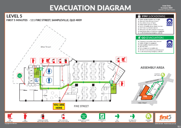
If we take a closer look at the above example, we can see a number of key elements which are included.
- The title ‘Evacuation Diagram’ in all capitals.
- A representation of ‘You Are Here’, which gives an occupant an understanding of where they are exactly.
- All of the designated exits which are located in that area or floor of the facility, colour coded in green.
- All communications equipment in the facility, and their locations.
- Locations of all hose reels, fire extinguishers & fire blankets, colour coded in red.
- Locations of fire indicator panels, which is an early detection & warning system designed to communicate evacuation directions to occupants.
- The validity date of the diagram, which expires 5 years after it has been created.
- Locations of assembly area(s) which can either be shown visually, or simply described in words.
- The legend containing all symbols used in the diagram.
- Paths of acceptable travel, colour coded in green.
- The sites address, postcode, access street location, nearest cross street and name.
- Any changes to the above in the facility, must be updated in the diagram.
As we can see, there is already a lot of information that is required to be in you evacuation plans to ensure they are compliant. However, that is not all of the information which could be contained in your diagrams.
If your sites Emergency Planning Committee decide any of these items are relevant, your diagrams may also contain;
- Direction of opening doors.
- First aid stations and kits, colour coded by a green and white cross.
- Emergency information as documented in the emergency plan.
- Fire and smoke doors.
- Fire hydrants, colour coded in red.
- Automatic External Defibrillators (AED).
- Electrical switchboard locations.
your own custom diagram
Do you need to update your Emergency Diagrams?
The AS3745:2010 framework outlines a wide assortment of requirements to ensure emergency evacuation diagrams are compliant. It can be easy to overlook these details, however they are absolutely vital in ensuring occupants are safe during the high-pressure experienced in emergencies.
By placing compliant diagrams around your facility, you ensure safe evacuation procedures are clearly laid out for anyone at your site. Our emergency evacuation diagrams are uniquely handcrafted by our team of expert designers, to ensure clear compliance for your organisation.
up next

Emergency Response Procedures
An emergency response procedure refers to the documentation containing all assigned responsibilities, actions and procedures within the emergency plan, to respond and manage emergencies.
your compliance benchmark
Discover the intricacies of Emergency Preparedness – and exactly where your lacking in compliance
Here’s our at-a-glance look at the sections of Australian Standard 3745:2010 Planning for Emergencies in Facilities that your facility should continue to consider and stay on top of to maintain your compliance.

Definitions
To assist with reading our fundamental guide to Emergency compliance, we’ve prepared a list of definitions for terms you may not be familiar with.

Emergency Planning Committee
The Emergency Planning Committee is a group of individuals who are responsible for the development, implementation and maintenance of the emergency plan, emergency response procedures and related training of a facility and its occupants.

Emergency Plan
The Emergency Plan is the master document which contains the organisational arrangements, systems, strategies, and procedures relating to the response and management of emergencies in a facility.

Emergency Control Organisation
Ensure your Chief Wardens and Wardens are prepared to take command and coordinate all aspects of an emergency. Your ECO members must gain an in-depth understanding of emergency procedures, from assessing risk that may be present in the workplace to effectively planning for all types of emergencies.

Emergency Preparedness Training
Training your facilities occupants will always be necessary for compliance, however the kind of training required differs based on that occupants role.

Emergency Response Exercises
Emergency Response Exercises are a site-specific exercise implemented to determine the effectiveness of emergency response procedures both when developed and on an on-going basis. These exercises are developed by the EPC in collaborations with facility owners, managers, occupiers, and employers of the facility.